Shurjoint Grooved Mechanical Couplings
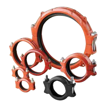
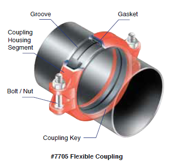
The Shurjoint grooved piping system is one of the most advanced, versatile, economical and reliable systems available today. After the pipe ends are grooved a gasket is mounted over the pipe ends. The coupling segments are then placed over the gasket and the bolts and nuts are fastened resulting in a secure and leak free joint.
A coupling can be installed 3 – 4 times faster than a comparable welded or brazed joint and there is no need for a flame or welding torch on the job site. A grooved mechanical coupling can be installed by fastening a pair of bolts and nuts while using only a wrench or spanner, whereas a comparable flanged joint requires the fastening of many bolts and nuts with a pair of wrenches. The grooved system allows for easy material take-offs and unlike a threaded system, there is no need to allow for added pipe length for thread engagement. With removal of just a few bolts one can easily access the system for cleaning, maintenance, changes and or system expansion.
Helpful Information to Ensure Proper Assembly
Some couplings and components require the housing bolt pads to make metal-to-metal contact for proper assembly, while others require a specific bolt torque while maintaining equal bolt pad gaps. The icons and information below will help to identify those items to ensure proper assembly. Read and follow all installation instructions for the component being installed.
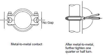
 Metal-to-metal contact: Tighten bolts and nuts until bolt pads make metal-to-metal contact. After metal-to-metal contact is achieved, tighten nuts by another one quarter or one half turn to make sure the bolts and nuts are snug and secure. No torque wrench is required. Excessive torque may lead to bolt or joint failure.
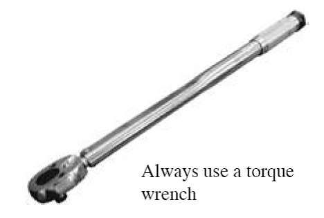
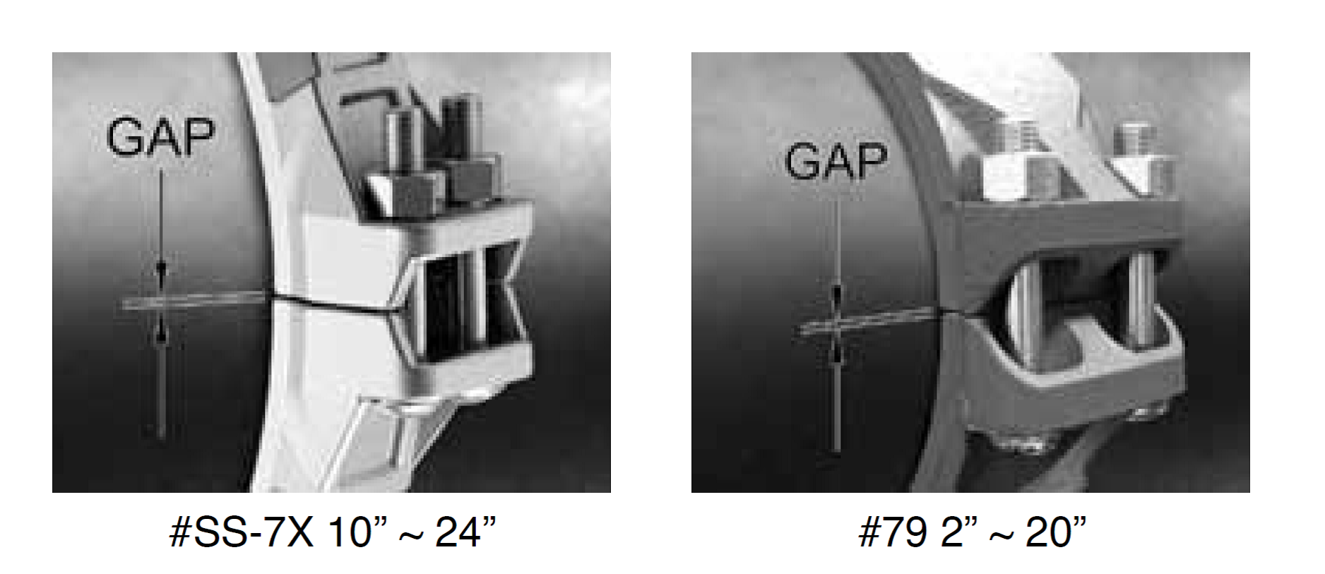
 Torque required! Bolts and nuts must always be tightened to the required torque by using a torque wrench. Normally there will be some gaps seen between the bolt pads after the bolts and nuts are fully tightened. Bolt pad gaps should be equal on both sides of the coupling. Models that require torque tightening include 2” through 4” of model XH-1000, all sizes of models XH-70EP, SS-7X and 79 couplings.
Rigid & Flexible Couplings
Grooved mechanical couplings (GMC) are available in both rigid and flexible models. A rigid coupling is used in applications where a rigid joint is desired, similar to that of a traditional flanged, welded, and or threaded connection. To be considered rigid, a coupling would allow less than one degree of deflection or angular movement.
Flexible couplings are designed to accommodate axial displacement, rotation and a minimum one degree of angular movement. Flexible couplings are used in applications that call for curved or deflected layouts and or when systems are exposed to outside forces beyond normal static conditions, such as seismic events or where vibration and or noise attenuation are a concern..
Grooved couplings become less flexible as the pipe size increases. For sizes in excess of 18” (450 mm) couplings are very limited in their angular movement. Please refer to the following definition and test methods.
Definition Grooved couplings are subjected to internal pressures and exterior bending forces during service. ASTM F1476-07 defines a rigid coupling as a joint where there is essentially no available free angular or axial pipe movement and a flexible coupling as a joint wherein there is available limited angular and axial pipe movement.
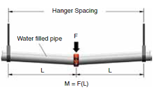
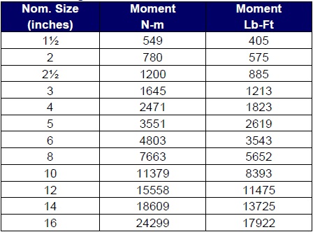
Bending Moment Test bending moments are calculated by the equation M = F (L), where F is weight of water filled pipe (Lbs) and L is hanger spacing x 1/2 (feet). The table below shows test bending moments calculated using sch. 40 pipe with NFPA 13 hanger spacing.
Test Bending Moment (ASTM F1476)
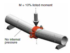
Flexibility Proof Test Flexibility proof testing is conducted by applying a small bending moment, 10% of the listed moment, to the test assembly with no internal pressure. A 4” model 7705 or 7707 flexible coupling deflects 3 – 4 degrees depending on the type of groove processed.
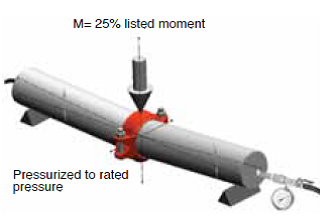
Rigidity Proof Test Rigidity proof testing is conducted by applying 25% of the listed moment to the test assembly which is internally pressurized to the rated pressure.
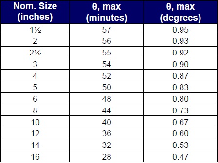
The rigid coupling shall pass the test when the angle has not changed more than angle θ. θ shall be calculated as follows: θ° = 60’ (minutes) – [2’ (minutes) x (nominal pipe
size in inches)]. In other words, when θ is less than 1 degree (60 minutes), the grooved mechanical coupling is verified as a rigid coupling and when θ is more than 1 degree (60 minutes), the GMC is regarded as a flexible coupling. The maximum angles θ for rigid couplings are shown in the table below:
Test Bending Moment (ASTM F1476)
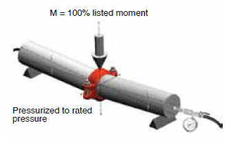
Bending Moment Proof Test The coupling shall resist a 100% listed bending moment while the assembly is internally pressurized to the rated pressure.