TYPICAL APPLICATIONS - FLEXIBLE COUPLINGS
- GENERAL SYSTEMS -
1. Absorption of vibration and noise
When a pump operates with frequent starts and stops, the piping system is affected by the noise and vibration of the equipment. The entire system may develop a large sway, referred to as sympathetic vibration, as a result of the frequent cycling. Shurjoint flexible couplings will help reduce such vibration and noise. The system should always be properly designed with steel angle sway braces to protect the system from large sways.
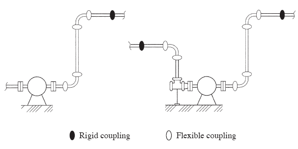
2. Adjustment of misalignment
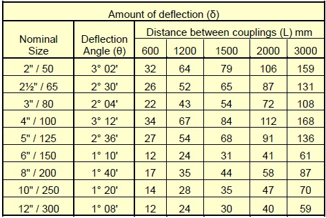
When a straight run has need for a slight adjustment of alignment on the jobsite as shown in the diagram, you can accomplish this with the use of two flexible couplings. The following table shows the deflection value (θ) of the Shurjoint 7705 flexible couplings.
.png)
3. Absorption of distortion
With the use of an assembly as shown below, ground sinking or movement around a tank or reservoir can be effectively absorbed, avoiding damage to the tank, reservoir and or the piping system.
.jpg)
4. Absorption of interfloor deflection
Risers of high-rise flexible structure buildings are subjected to lateral sways (inter-floor deflection) when an earthquake occurs. If we assume the inter-floor deflection (α) as 1/150 and the floor height (H) as 4 meters, the estimated interfloor deflection (α) will be:
α = H x 1/150 = 4000 x 1/150 = 27mm
If we use a 8" (200mm) 7707 coupling for each floor, the maximum deflection (β) that each coupling can accommodate will be;
β = L x tanθ = 4000 x 0.02915 = 4.56”= 116mm (θ = 1.67°)
The example shows a flexible coupling would be sufficient enough to absorb this scale of seismic sways.
.jpg)
5. Absorption of misalignment
As shown in the diagram, each branch connection to the free riser will be subjected to serious shearing forces as pressure thrusts or thermal movement increases. By using two flexible couplings, you can solve this problem.
.jpg)
6. Curved layout
With Shurjoint flexible couplings you can design a slowly curved layout for a system along a curved tunnel, winding road or curved building.
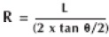 (where: R is radius of curvature, L is pipe length, and θ is max. allowed deflection of a coupling)
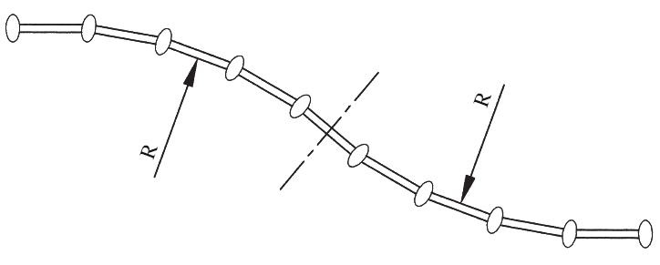
Example: When using model 7705 100mm (4") coupling for the layout as shown in the diagram, the max. allowed deflection (θ) of the coupling is 3.4°, and the pipe length (L) is 5.5 meters, the radius of curvature (R) will be 92.7 meters.
7. Absorption of Thermal Stress
Thermal stress is caused by changes in temperature, resulting in either expansion or contraction. With the use of Shurjoint flexible couplings you can design your system to accommodate such movement without the need for costly expansion joints. The thermal expansion or contraction (μ) is determined by the length of pipe (L) and temperature difference (△T).
μ = α x L x △T
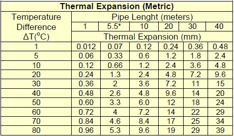
*5.5 meters is the standard length of commercial carbon steel pipe.
As the liner expansion coefficient for steel (α) is 1.2 x 10⁻⁵, you can use the table above to determine the thermal expansion.
Example:
- Pipe size: 4”(100mm)
- Max. pipe end separation (E): 3.2mm
- Pipe length (L): 5500 mm
- Temperature difference (△T): 40o C (+5o C to +45o C)
- α= 1.2 x 10⁻⁵
μ= αx L x △T = 1.2 x 10-5 x 5500 mm x 40o C = 2.64mm
The thermal expansion of a 5.5 meter standard length of pipe (μ) is within the allowance (= max. pipe end separation) of a flexible coupling. In other words, if you use a coupling for each pipe length of 5.5 meters, the coupling will accommodate the thermal expansion or contraction expected to take place for a 40oC temperature change. When you calculate the necessary number of couplings (N) for an anchored system, you should place a clearance of N x E x 1/2 as a safety factor.
Whether it is thermal expansion, contraction, or a combination thereof, the system requires suitable anchor installations with properly space alignment guides and weight support devices. Where and when larger thermal movement is anticipated, you should use supplementary expansion joint(s).
For installers who use the imperial units of measure, the following table will be more convenient.
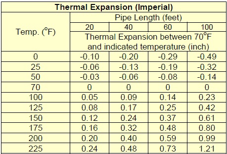
*Coefficient of thermal expansion of steel pipe = 6.33 in/in. oF x 10-6
TYPICAL APPLICATIONS - FLEXIBLE COUPLINGS–SPRINKLER SYSTEMS (NFPA 13)
The following illustrations are part of NFPA 13 – 2013 Annex A Explanatory Material. These are for informational purposes only and not a mandatory requirement. For specific requirements for any other areas of sprinkler systems, refer to the latest version of NFPA 13.
1. Flexible couplings for main risers and branch line riser
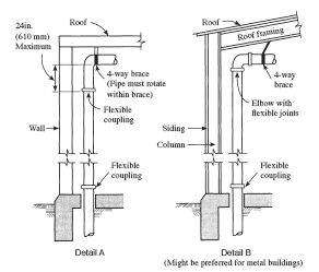
Note to Detail A: The four-way brace should be attached above the upper flexible coupling required for the riser and preferably to the roof structure if suitable. The brace should not be attached directly to a plywood or metal deck.
FIGURE A.9.3.2(a) Riser Details.
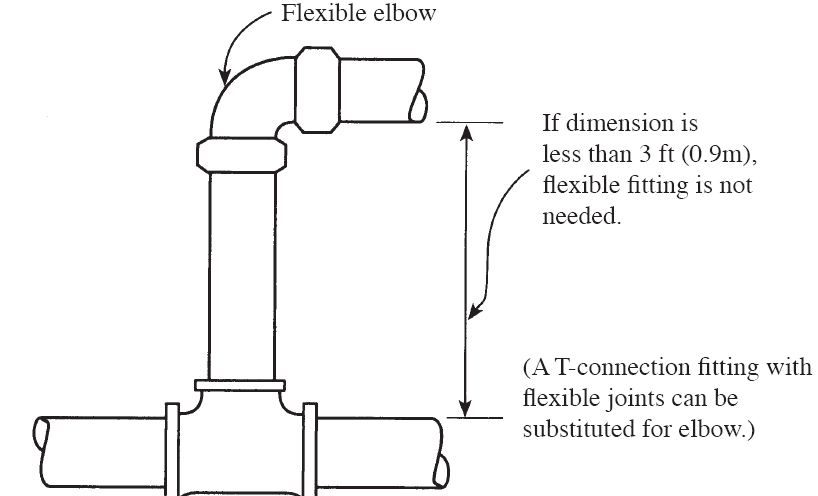
FIGURE A.9.3.2(b) Detail at Short Riser
2. Flexible couplings on horizontal portion of Tie-In
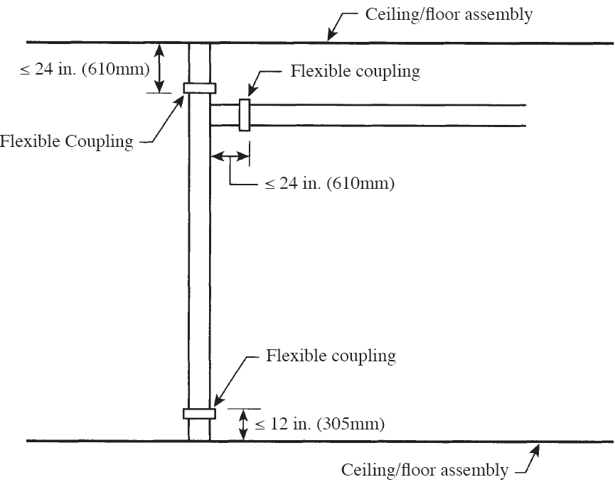
FIGURE A.9.3.2.3(2) Flexible Coupling on Horizontal Portion of Tie-In.
3. Flexible Coupling on Main Riser and Branch Line Riser
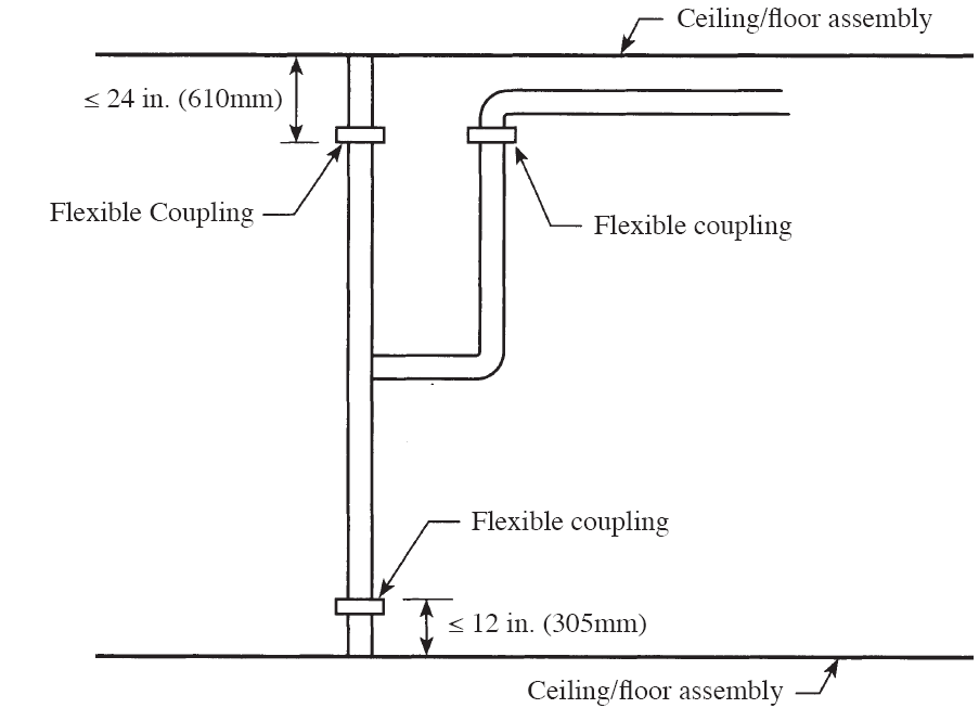
FIGURE A.9.3.2.3(2) Flexible Coupling on Main Riser And Branch Line Riser
4. Flexible couplings for drops
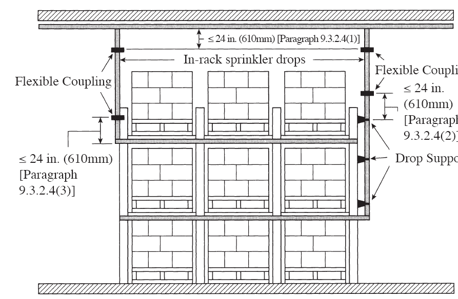
FIGURE A.9.3.2.4 Flexible Coupling for Drops
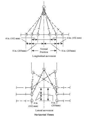
5. Seismic Separation Assembly
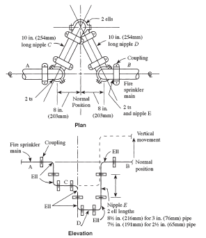
FIGURE A.9.3.3(a) Seismic Separation Assembly. Shown are an 8 in. (203 mm) Separation Crossed by Pipes up to 4 in. (102mm) in Nominal Diameter. For other separation distances and pipe sizes, lengths and distances should be modified proportionally.
6. Earthquake protection for sprinkler piping
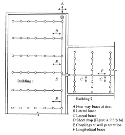
FIGURE A.9.3.5.9 (a)
7. Typical Location of Bracing on a Looped System
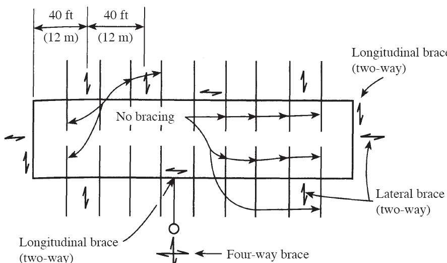
FIGURE A.9.3.5.6 (d) Typical Location of Bracing on a Looped System.
Systems having more flexible couplings than required above shall be provided with additional sway bracing. Alateral brace shall be provided within 24”(600mm) of every other coupling unless pipes are supported by rods less than 6" (152mm) long from the ceiling or by U-type hooks underside of the structural element. (NFPA 13 – 2013 9.3.2. & 9.3.5.)