Roll Grooving Dimensions for ANSI B36.10, BS 1387 (M) & AS 1074 (M) Pipe
Basic roll groove dimensions conform to ANSI/AWWA C606-06 Table 5 with slightly adjusted tolerances to incorporate international standards including CSA B242, ISO/FDIS 6182-12, VdS 2100-6en and JPF MP-006.
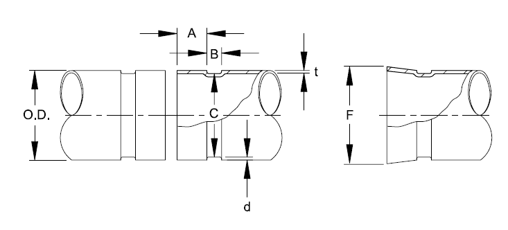
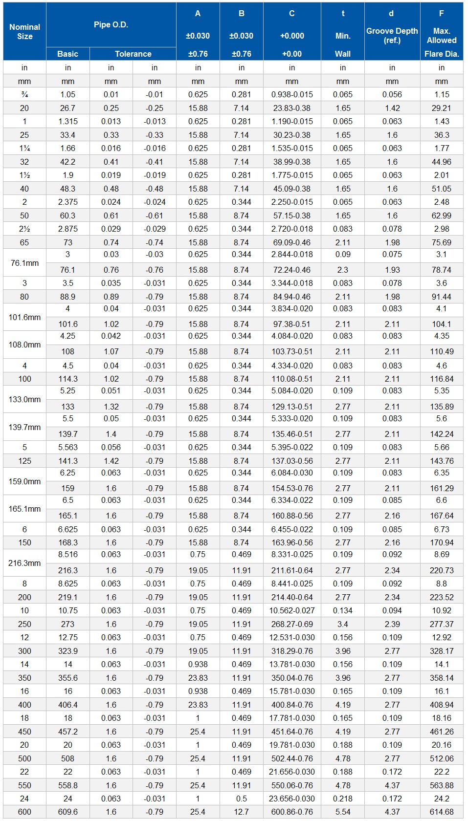
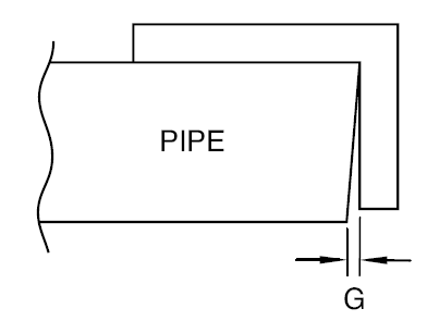
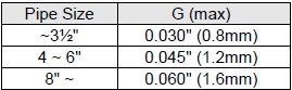
1. Pipe ends must be square cut. See above table for maximum allowable tolerances from square cut ends
2. The gasket seating surface `A' shall be free from deep scores, marks, or ridges that would prevent a positive seal.
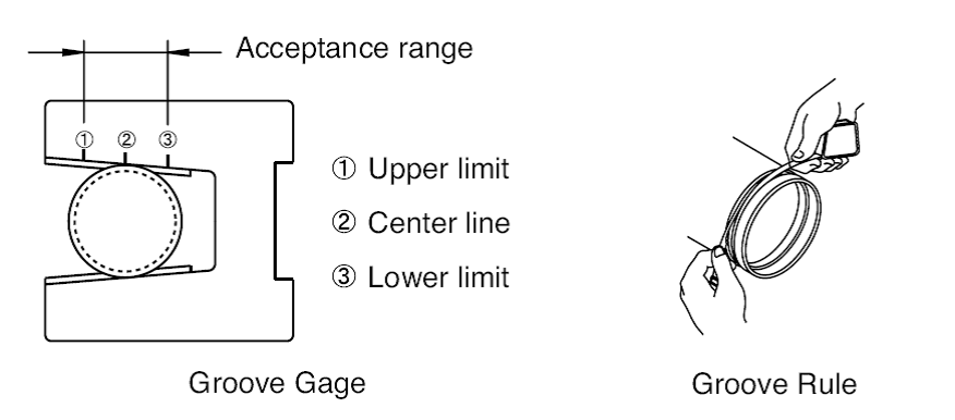
3. The `C' dimensions are average values. The groove must be of uniform depth around the entire circumference. Use a Shurjoint groove gage or rule to check the groove diameter.
4. The `t' is the minimum allowable wall thickness that may be roll-grooved.
5. The `d' is for reference use only. The groove depth shall be determined by the groove diameter `C'.
6. Flare Diameter: The pipe end that may flare when the groove is rolled shall be within this limit when measured at the extreme end of the pipe.